Welding position has a major influence on how easily a welder can control the molten weld pool, maintain consistent penetration, and produce a sound weld.
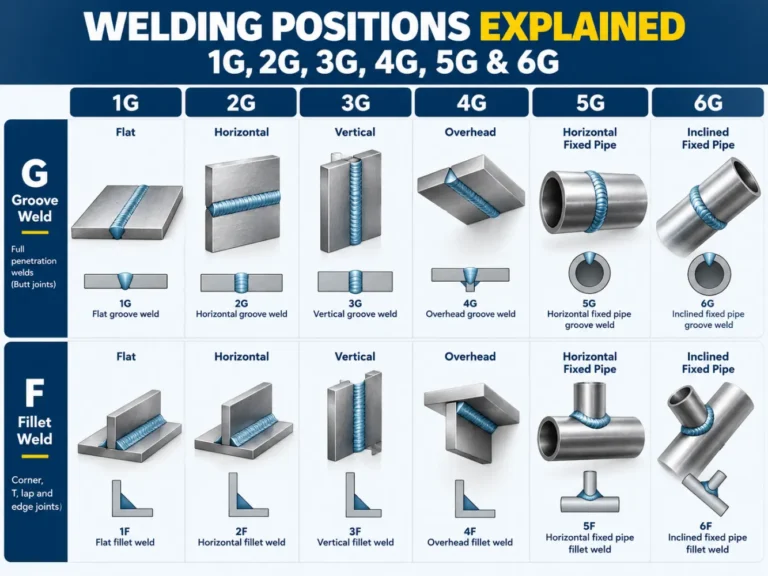
The most common welding positions are identified as 1G, 2G, 3G, 4G, 5G, and 6G. The number describes the welding position, while the letter indicates the type of weld. In this system, G stands for groove weld, while F stands for fillet weld.
For fabrication shops, welding position is also closely related to workpiece handling. A fixed pipe may require the welder to work through several orientations around its circumference, while a pipe mounted on a welding positioner can be rotated at a controlled speed to keep the weld in a more favorable working position.
This guide explains the main welding positions, their differences, and how welding positioners and chucks can help improve workpiece positioning in production.
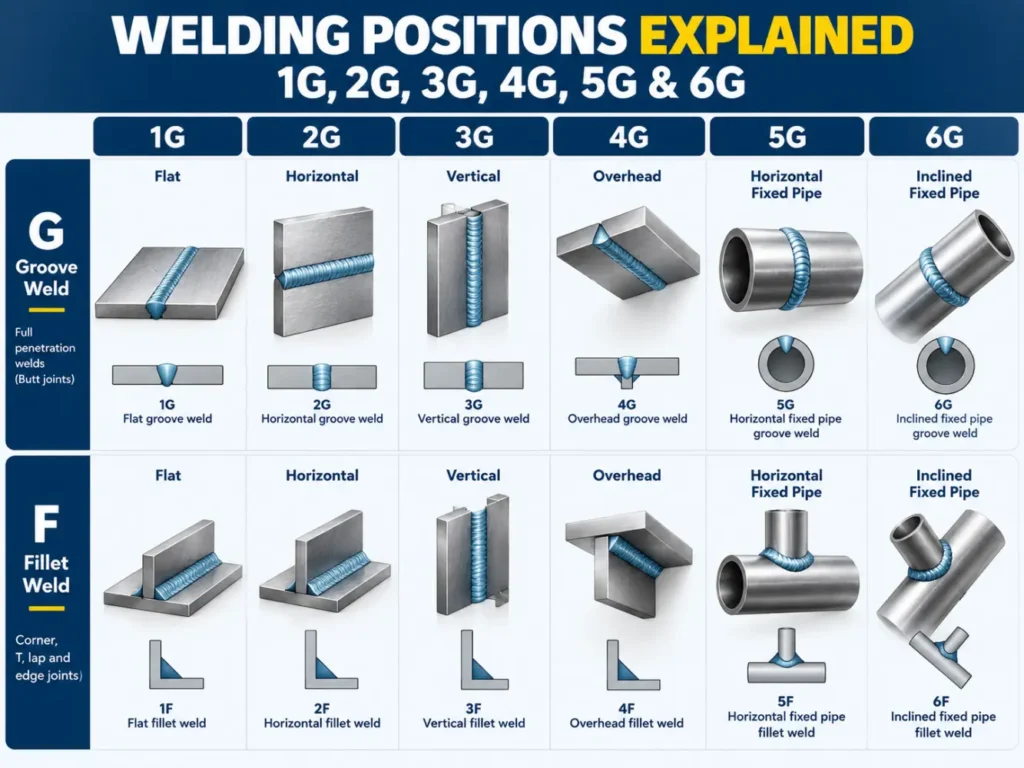
What Do 1G, 2G, 3G, 4G, 5G and 6G Mean?
The basic welding positions describe the relationship between the weld joint, the workpiece, and the welder.
| Welding Position | Basic Orientation | Workpiece Movement | Relative Difficulty |
| 1G | Flat | Plate fixed; pipe may rotate in applicable setups | Easy |
| 2G | Horizontal | Fixed | Moderate |
| 3G | Vertical | Fixed | Difficult |
| 4G | Overhead | Fixed | Difficult |
| 5G | Horizontal fixed pipe | Pipe does not rotate | Difficult |
| 6G | Fixed pipe at an inclined angle | Pipe does not rotate | Very difficult |
In general, flat welding is easier because gravity helps keep the molten weld pool in the joint. As the weld moves into vertical or overhead orientations, controlling the weld pool becomes more difficult.
Pipe welding introduces another challenge because the welding orientation can continuously change as the welder progresses around a fixed pipe.
Fixed Welding Position vs Workpiece Positioning
This is where welding positioning equipment becomes important.
A fixed workpiece determines where and how the welder must work. A positioner allows the orientation of the workpiece to be changed to improve access to the joint.
| Fixed Workpiece | Workpiece on Welding Positioner |
| Welder moves around the workpiece | Workpiece can rotate |
| Welding orientation may change | Orientation can be controlled |
| Difficult torch access may occur | Workpiece can be tilted for access |
| More operator movement | Reduced operator movement |
| Travel speed depends heavily on operator | Controlled rotation is possible |
| Automation can be difficult | Well suited to automated welding |
This difference becomes especially significant when producing repeated circumferential welds.
Fixed Welding Position vs Workpiece Positioning
A welding positioner supports and moves a workpiece during welding.
Two movements are particularly useful:
Rotation
The positioner rotates the workpiece around an axis.
For pipe welding, this allows the pipe to rotate beneath a welding torch at a controlled speed.
A typical arrangement is:
Welding Torch → Weld Joint → Rotating Pipe → Welding Positioner
Controlled rotation can help maintain a more consistent relationship between:
- Welding speed
- Torch position
- Workpiece
- Weld joint
This is particularly useful for circumferential welding.
Tilting
Many welding positioners also allow the table to tilt.
Changing the table angle changes the orientation of the weld joint relative to the operator and gravity.
Depending on the equipment, the workpiece can therefore be both: Rotated + Tilted
This is especially useful for flanges, fittings, tanks, cylindrical assemblies, and complex fabricated components.
What Is the Role of a Welding Chuck?
The positioner moves the workpiece, but it still needs to be held securely.
This is the role of the welding chuck.
A typical rotary welding system consists of:
Welding Positioner → Welding Chuck → Workpiece → Welding Torch
The positioner provides controlled movement, while the chuck provides workholding.
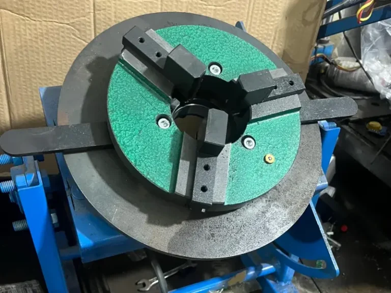
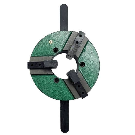
For round components, a 3 jaw chuck for a welding positioner can provide fast and convenient clamping of:
- Pipes
- Tubes
- Flanges
- Rings
- Fittings
- Cylindrical components
Depending on the chuck design, the workpiece may be held by its outside diameter or clamped through an internal diameter.
For irregular or eccentric workpieces, an independently adjustable chuck or dedicated fixture may be more appropriate.
Welding Positioner vs Welding Rotator
Although both systems rotate workpieces, they are designed for different applications.
A welding positioner typically supports the workpiece from a rotating table or chuck. It is suitable for components such as pipes, flanges, fittings, and smaller vessels.
A welding rotator, also known as a welding turning roll, supports cylindrical workpieces on rollers.
Rotators are commonly used for:
- Large tanks
- Pressure vessels
- Long cylindrical shells
- Large-diameter pipes
The correct solution therefore depends on workpiece geometry, size, weight, and welding process.
Which Welding Position Is Best?
There is no single welding position that is best for every application.
Welder qualification positions are used to demonstrate the ability to weld under specified conditions. Production welding has a different objective: achieving the required weld quality safely, consistently, and efficiently.
When a workpiece cannot be moved, the welder must adapt to the required position.
When the workpiece can be moved, positioning equipment may allow the manufacturer to establish a more favorable welding orientation.
This can be particularly beneficial for repetitive fabrication, where every component follows a similar welding sequence.
How to Choose a Welding Positioner
Selecting a positioner based only on workpiece weight can result in an unsuitable or unsafe setup.
Several factors should be considered together.
Workpiece Weight
The rated capacity must accommodate the complete rotating load.
This may include:
Workpiece + Chuck + Fixture + Adapter Plate
- Workpiece Diameter
- Large-diameter components may move the center of gravity farther from the positioner table.
- Workpiece Length
- Long pipes and components can generate substantial moment loads even when their total weight appears relatively low.
- Center of Gravity
- The relationship between the center of gravity and the positioner table is one of the most important factors in positioner selection.
- Rotation Speed
- The required speed depends on workpiece diameter and desired welding travel speed.
- Tilt Requirement
- Determine whether rotation alone is sufficient or whether the workpiece must also be tilted.
- Chuck or Fixture
- The workholding system must be compatible with both the workpiece and the positioner table.
- Welding Process
- Positioners can be used with many welding processes, including TIG, MIG/MAG, plasma, and other manual or automated welding systems.
Choosing the Right Welding Chuck
When a welding chuck is required, consider:
- Workpiece outside diameter
- Workpiece inside diameter
- Chuck clamping range
- Workpiece weight
- Chuck weight
- Number and type of jaws
- Internal or external clamping
- Positioner table diameter
- Mounting-hole pattern
- Required concentricity
- Center of gravity
A larger chuck does not automatically mean that a positioner can handle a larger workpiece.
The chuck itself adds weight and may increase the distance between the workpiece center of gravity and the positioner table.
The complete rotating system should therefore be evaluated rather than considering chuck diameter alone.
Welding Positions in Manual and Automated Welding
Welding position becomes even more important when moving from manual welding toward mechanized or automated production.
With manual welding, the welder continuously adjusts torch angle, travel speed, and body position.
With a properly configured positioning system, movement can instead be controlled through the equipment.
For example:
Fixed Torch + Controlled Workpiece Rotation
can be used to produce repetitive circumferential welds.
Depending on the application, this can help improve repeatability while reducing unnecessary operator movement.
The positioner does not replace the welding procedure or welding expertise. Instead, it provides a more controlled platform for workpiece movement.
Improve Welding Access Through Better Workpiece Positioning
Understanding 1G, 2G, 3G, 4G, 5G, and 6G welding positions is important for welders, engineers, and fabrication shops.
But welding position is not only about the welder.
In production environments, the way the workpiece is held, rotated, and tilted can have a major influence on welding accessibility and consistency.
A properly selected combination of:
Welding Positioner + Welding Chuck + Workpiece Fixture
can make it possible to control workpiece orientation rather than requiring the operator to continuously adapt to difficult welding positions.
MECBASE provides welding positioners, welding chucks, and workpiece positioning solutions for pipe, flange, fitting, and general fabrication applications.
Frequently Asked Questions
Yes. Welding positioners are commonly used for TIG welding, particularly for circumferential welds on pipes, tubes, flanges, and cylindrical components. The required rotation speed should be matched to the welding process and workpiece diameter.
Yes. Positioners can be integrated with MIG/MAG welding for both manual and automated applications, provided the equipment capacity and rotation range are suitable.
Yes. The chuck, fixture, adapter plate, and workpiece all contribute to the load carried by the positioner.
Possibly, but the mounting interface, chuck weight, workpiece weight, center of gravity, and allowable positioner load must all be checked. Chuck diameter alone is not enough to determine compatibility.
The required rotational speed depends primarily on the pipe diameter and desired welding travel speed. A larger-diameter pipe generally requires a lower rotational speed to achieve the same linear weld travel speed.
A 3-jaw chuck is convenient for repetitive clamping of regular round components. A 4-jaw or independently adjustable chuck can provide greater flexibility for irregular, eccentric, or non-round workpieces.