What Is a Welding Chuck?
A welding chuck is a workholding device used to grip, position, center, and sometimes rotate a workpiece during welding.
It is commonly used for round components such as pipes, tubes, flanges, tanks, cylinders, and other fabricated parts.
In many welding applications, maintaining accurate alignment and stable rotation is important for producing a consistent circumferential weld. A welding chuck securely holds the workpiece while it is rotated manually or by equipment such as a welding positioner, rotary table, or welding lathe.
Although welding chucks may look similar to lathe chucks, they are designed primarily for welding and fabrication applications rather than precision machining.
How Does a Welding Chuck Work?
A typical welding chuck uses multiple jaws arranged around the center of the chuck.
For a three-jaw welding chuck, the basic working principle is:
Workpiece → Jaw Clamping → Centering → Rotation → Welding
The operator places the pipe, flange, or cylindrical component between the jaws. The jaws are then tightened to secure the workpiece.
When the chuck is mounted on a welding positioner, the complete assembly can rotate during welding.
This allows the welding torch to remain in a relatively stable position while the weld joint moves past it at a controlled speed.
This arrangement is particularly useful for:
- Circumferential pipe welding
- Pipe-to-flange welding
- Tank and vessel fabrication
- Tube fabrication
- Automated welding systems
- Repetitive production welding
Welding Chuck vs. Lathe Chuck
A common question is whether a welding chuck and a lathe chuck are the same.
They are similar in appearance and basic clamping principle, but their applications are different.
| Feature | Welding Chuck | Lathe Chuck |
| Main purpose | Welding and fabrication | Machining |
| Typical equipment | Welding positioner | Lathe |
| Typical workpieces | Pipe, flange, cylinder | Shaft, bar, machined component |
| Rotation speed | Usually relatively low | Can be much higher |
| Main requirement | Stable holding and rotation | High machining accuracy and rigidity |
| Large diameter capability | Common | Depends on machine |
| Through-bore designs | Common for pipe applications | Also available |
A welding chuck should therefore be selected according to the requirements of the welding equipment rather than simply replaced with a similarly sized machining chuck.
Main Types of Welding Chucks
There is no single universal classification system for welding chucks. Manufacturers may use different model names and series.
However, welding chucks can generally be classified according to their structure, jaw arrangement, clamping mechanism, and application.
Manual Welding Chuck
A manual welding chuck uses a mechanical mechanism to open and close the jaws.
The operator normally uses a handle, wrench, screw, or similar mechanism to adjust the jaws.
Manual welding chucks are popular because they offer:
- Simple construction
- Easy operation
- Relatively low maintenance
- No hydraulic or pneumatic power requirement
- Good suitability for small-batch fabrication
They are widely used with manual and semi-automatic welding positioners.
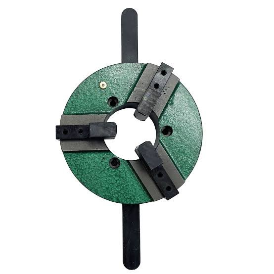
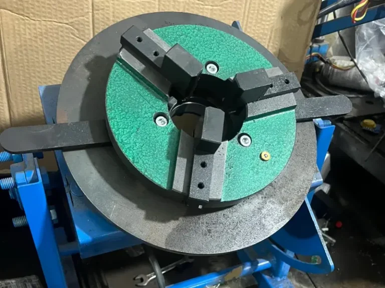
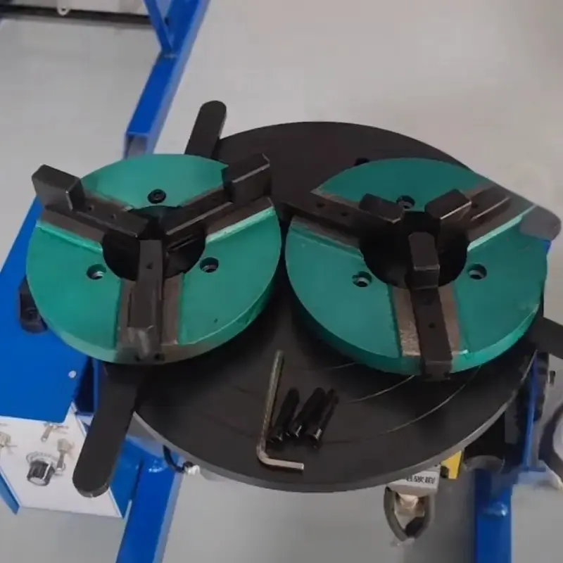
Three-Jaw Welding Chuck
The 3-jaw welding chuck is one of the most common designs for holding round workpieces.
Three jaws are positioned approximately 120 degrees apart.
This configuration provides good support for:
- Pipes
- Tubes
- Flanges
- Cylindrical vessels
- Round fabricated components
Three-jaw designs are particularly convenient when the workpiece needs to be centered relative to the rotation axis.
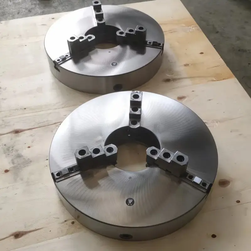
Four-Jaw Welding Chuck
A four-jaw welding chuck uses four clamping jaws.
Depending on the design, the jaws may move together or independently.
Independent-jaw designs provide greater flexibility when holding:
- Square components
- Irregular workpieces
- Off-center components
- Fabricated assemblies requiring individual adjustment
However, centering can require more setup time than with a self-centering three-jaw chuck.
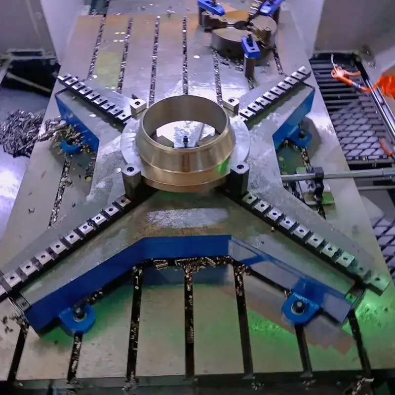
Self-Centering Welding Chuck
A self-centering welding chuck uses mechanically linked jaws.
When the operator adjusts the chuck, all jaws move simultaneously toward or away from the center.
The main advantage is faster setup.
For repetitive production involving round pipes or cylinders of similar sizes, self-centering chucks can significantly simplify workpiece positioning.
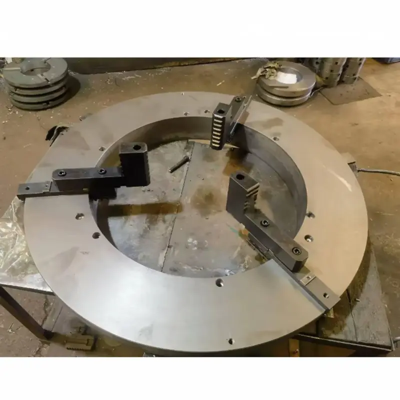
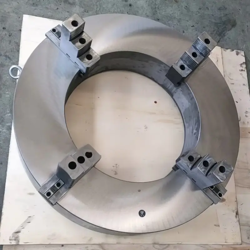
Large Through-Bore Welding Chuck
A large through-bore welding chuck has a large central opening that allows pipes or cylindrical components to pass through the chuck body.
This is especially useful for long pipe fabrication.
Instead of positioning the entire pipe in front of the chuck, part of the pipe can extend through the center opening.
Large-bore welding chucks are commonly used for:
- Long pipes
- Large-diameter tubes
- Pipeline components
- Pressure vessel fabrication
- Pipe spool production
Open-Type Welding Chuck
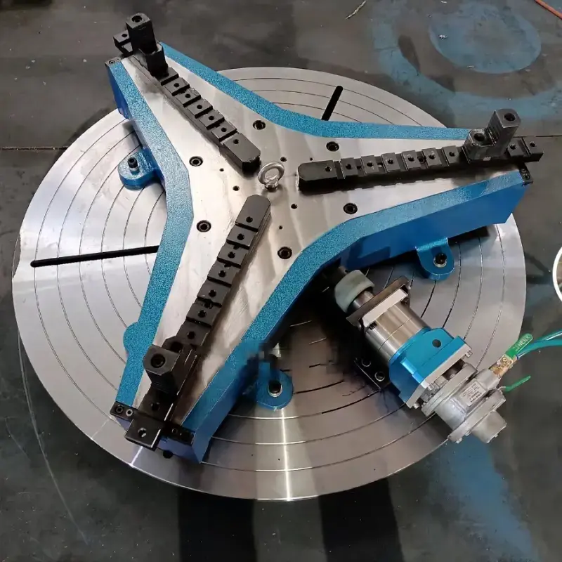
An open-type welding chuck uses arms or extended jaw supports instead of a complete circular chuck body.
One major advantage is the potentially large clamping range.
This design can be useful when a fabrication shop handles many different pipe diameters and wants one chuck to cover a broader range of workpieces.
Pneumatic and Hydraulic Welding Chucks
For higher-volume or automated production, manual clamping may become inefficient.
A pneumatic welding chuck uses compressed air to operate the jaws, while a hydraulic welding chuck uses hydraulic pressure.
These systems can provide:
- Faster loading and unloading
- More repeatable clamping
- Easier integration with automated welding equipment
- Reduced operator intervention
Hydraulic systems can also provide high clamping forces for heavy workpieces.
Standard Jaws vs. Reversed Jaws
Many manual welding chucks allow the jaws to be installed in different orientations.
Standard Jaws
- Standard jaw orientation is generally used for smaller workpiece diameters.
- For example, a large manual chuck might have a standard-jaw clamping range such as:
- Ø150–410 mm
Reversed Jaws
- The jaws can sometimes be reversed to accommodate larger diameters.
- The same chuck might then provide a range such as:
- Ø400–620 mm.
- This greatly increases the useful working range without requiring another chuck.
What Are Extended Jaws?
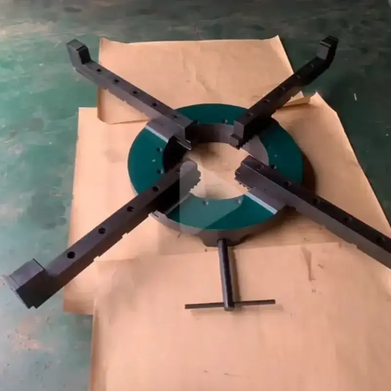
Some welding chucks can use extended jaws, extension tubes, or jaw extensions.
These accessories move the clamping surface farther from the center of the chuck.
As a result, the chuck can accommodate components considerably larger than its normal jaw range.
However, increasing the effective clamping diameter also changes the mechanical loading on the chuck.
The manufacturer’s permitted load, workpiece center of gravity, rotational speed, and positioner capacity should therefore always be considered.
Welding Chuck and Welding Positioner
A welding chuck and a welding positioner are related but are not the same thing.
The chuck holds the workpiece.
The positioner rotates and positions the workpiece.
A typical system can be represented as:
Workpiece → Welding Chuck → Welding Positioner → Drive System
When selecting a chuck for an existing welding positioner, compatibility between the two components is critical.
Important mounting information may include:
- Mounting bolt quantity
- Bolt size
- Bolt circle diameter
- Chuck mounting interface
- Positioner table diameter
- Center hole dimensions
A chuck with sufficient workpiece capacity may still be unsuitable if its mounting interface does not match the positioner.
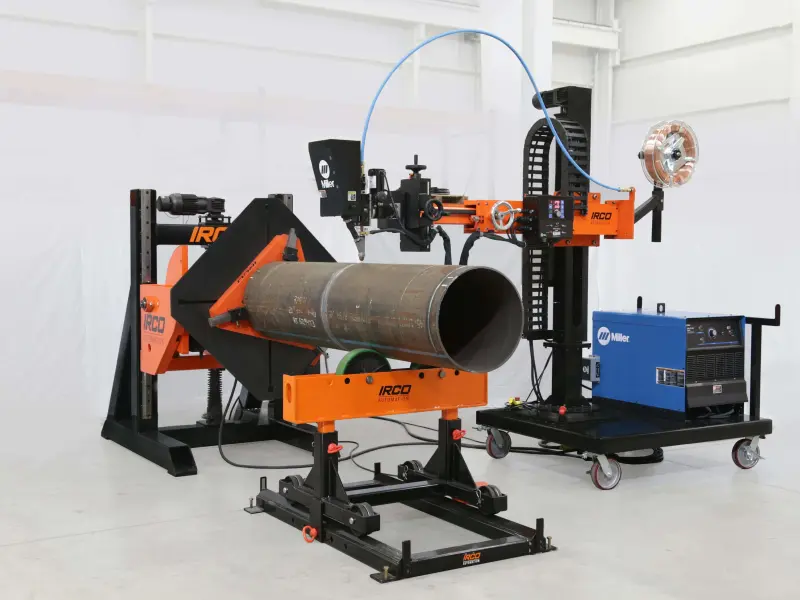
Where Are Welding Chucks Used?
Welding chucks are used throughout metal fabrication industries.
Typical applications include:
- Pipe Fabrication
- The chuck holds the pipe while the workpiece rotates during circumferential welding.
- Pipe-to-Flange Welding
- A flange and pipe can be aligned and rotated together to produce a more consistent circumferential weld.
- Pressure Vessel Manufacturing
- Large chucks can support cylindrical sections and components during fabrication.
- Tank Manufacturing
- Circular tank components may be positioned for longitudinal or circumferential welding.
- Boiler and Heat Exchanger Fabrication
- Tube and pipe assemblies often require controlled positioning during welding.
- Automated Welding
- A chuck can become part of an automated system incorporating a welding positioner, controller, welding torch, and other equipment.
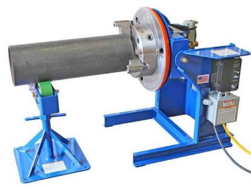
How to Select a Welding Chuck
Choosing a welding chuck based only on its nominal diameter or model number can lead to problems.
The following specifications should be checked.
| Parameter | Why It Matters |
| Clamping Range | Determines the minimum and maximum workpiece diameter |
| Standard-Jaw Range | Working range with jaws in normal orientation |
| Reversed-Jaw Range | Maximum range when jaws are reversed |
| Load Capacity | Determines allowable workpiece weight |
| Chuck Diameter | Affects size and positioner compatibility |
| Through-Bore Diameter | Important for long pipes |
| Mounting Dimensions | Determines compatibility with the positioner |
| Jaw Type | Influences workpiece geometry and centering |
| Chuck Weight | Must be included in total positioner loading |
| Workpiece C.G. | Important for safe positioner operation |
| Required Rotation Speed | Must be compatible with the welding process |
Don't Select a Welding Chuck by Model Number Alone
This is particularly important when sourcing welding chucks internationally.
Names such as:
WP600, WPS600, WPT600
may be manufacturer-specific model designations rather than internationally standardized welding chuck sizes.
For example, two manufacturers may both offer a “600” series chuck while providing different:
- Clamping ranges
- Chuck diameters
- Through-hole dimensions
- Mounting patterns
- Jaw structures
- Load capacities
Therefore, when requesting a quotation, it is better to provide the actual technical requirements.
A typical RFQ should state:
Manual 3-jaw welding chuck
Workpiece diameter range: ___ mm
Maximum workpiece weight: ___ kg
Required through-bore: ___ mm
Positioner table diameter: ___ mm
Mounting hole/bolt pattern: ___
Rotation speed: ___ rpm
Application: pipe / flange / vessel / other
Drawings or photographs of the existing positioner are also useful when selecting a replacement chuck.
Conclusion
A welding chuck is an important workholding component for pipe welding, flange fabrication, vessel manufacturing, and welding automation.
While different manufacturers use different model names, the basic selection principles remain the same.
The most important factors are not simply the model number, but the clamping range, jaw configuration, load capacity, through-bore size, mounting dimensions, workpiece center of gravity, and compatibility with the welding positioner.
Understanding these parameters makes it much easier to select a suitable manual welding chuck or replacement chuck for a specific welding application.
FAQs About Welding Chucks
No. The chuck grips the workpiece, while the positioner provides controlled rotation or angular positioning. A welding chuck is frequently mounted directly onto a welding positioner.
A manual welding chuck uses a mechanically operated jaw system instead of pneumatic or hydraulic actuation. It is commonly used for general pipe and fabrication work.
Three-jaw chucks are primarily used for round workpieces such as pipes, tubes, flanges, and cylindrical components.
It should not automatically be interpreted as an industry-standard size. Model designations are often defined by individual manufacturers. Always verify the manufacturer's dimensional and performance specifications.
Many designs allow reversed jaws to increase the available clamping diameter. The exact range depends on the chuck design.
Yes. Welding chucks are commonly used to hold pipes, flanges, rings, and other circular fabricated components, provided that the jaw configuration and rated capacity are suitable.
At minimum, specify the workpiece diameter range, maximum weight, chuck type, mounting dimensions, through-bore requirement, positioner information, and application.