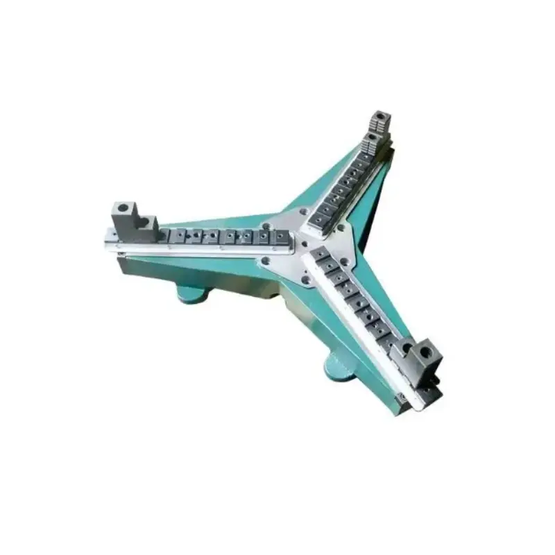
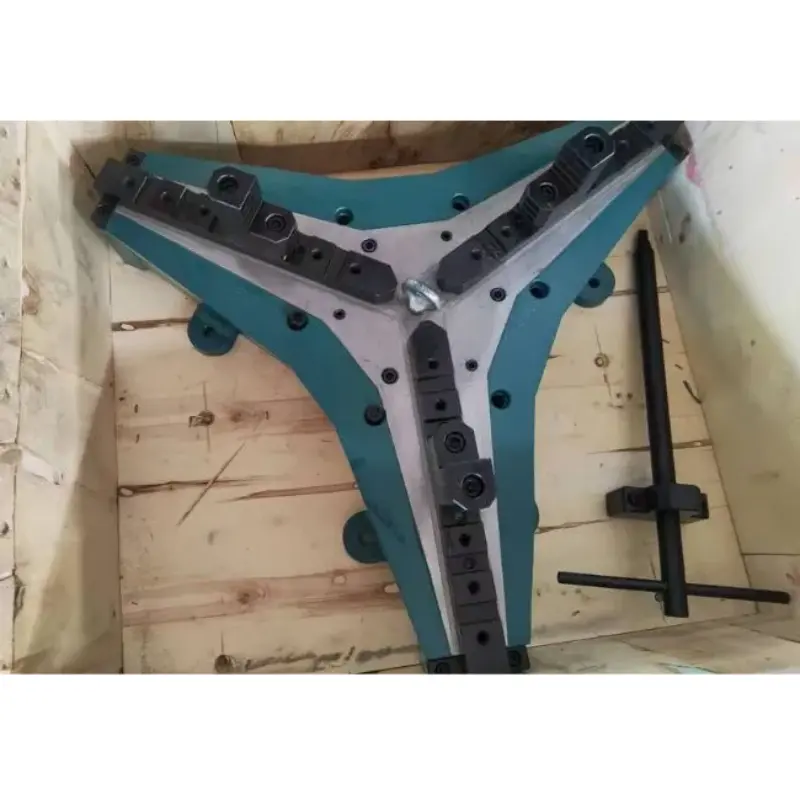
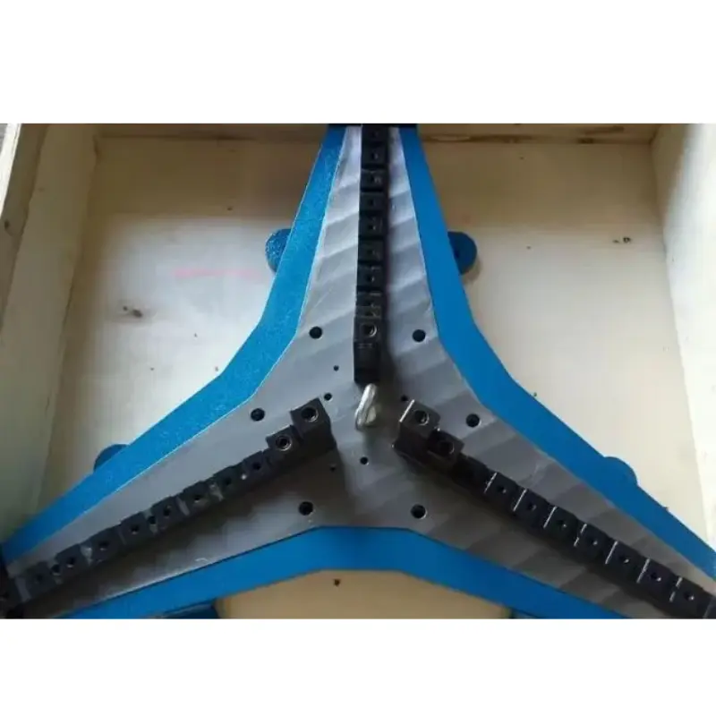
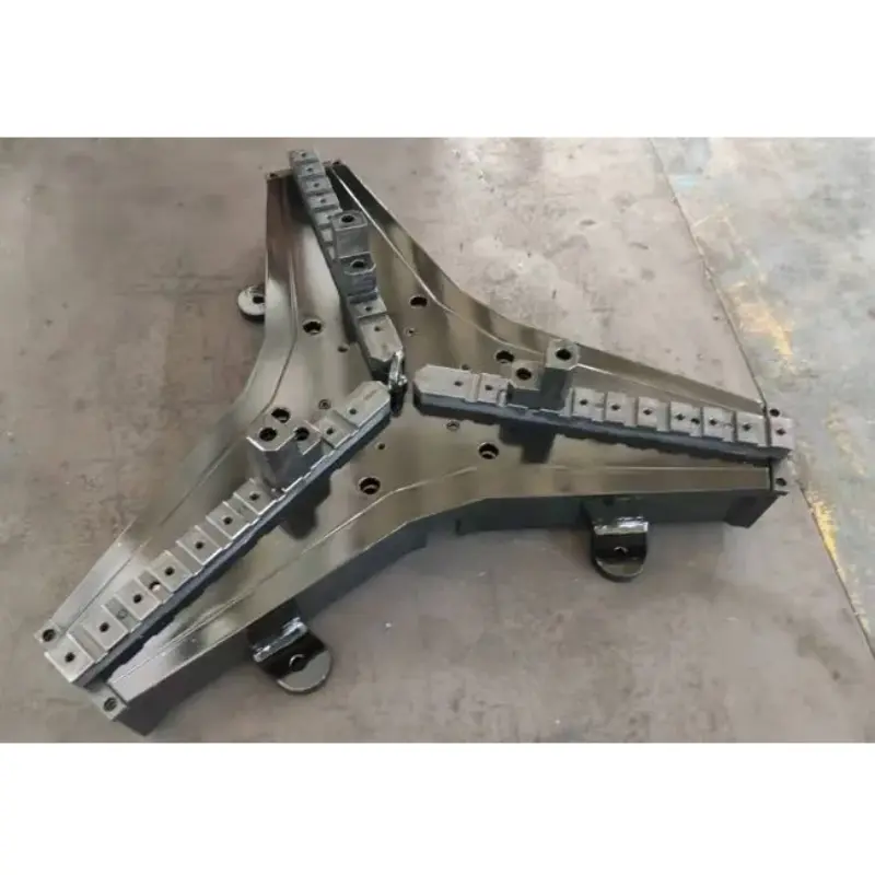
WPT Welding Chucks

Wide-Range Self-Centering Chucks for Welding Positioners

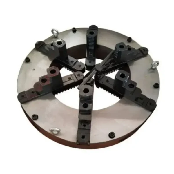
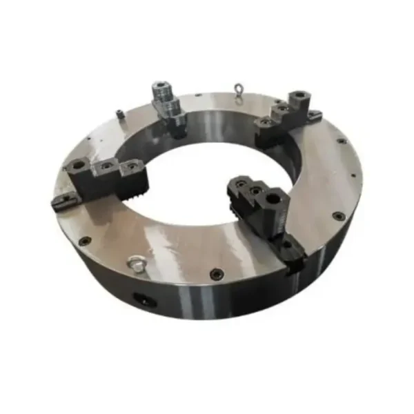
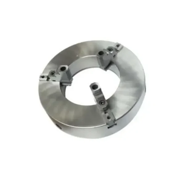
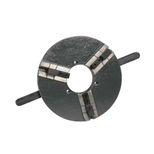
WPT Welding Chucks are self-centering workholding chucks designed primarily for welding positioners and welding or cutting equipment.

The WPT Series combines a wide clamping range with high load capacity, allowing large pipes, cylinders and other workpieces to be centered and securely clamped during welding and positioning operations.

With models covering clamping diameters up to Ø2000 mm and specified load capacities up to 2000 kg, WPT Welding Chucks are suitable for applications requiring large workpiece capacity and flexible diameter coverage.

The series is designed for accurate self-centering, convenient manual operation and efficient workpiece setup in repetitive welding and cutting applications.

Available Models: WPT600 – WPT2000
Clamping Range: Up to Ø2000 mm
Maximum Clamping Force: Up to 70 kN
Load Capacity: Up to 2000 kg

WPT Series Manual Welding Chuck Features

Wide Clamping Range

WPT models cover workpiece diameters from Ø100 mm to Ø2000 mm, depending on the selected model.

This makes the series particularly suitable for workshops handling different pipe, cylinder and fabricated component diameters.

Self-Centering Clamping

The WPT Series is designed to center and clamp the workpiece, reducing the amount of manual alignment required during workpiece setup.

High Load Capacity

Depending on model, specified load capacity ranges from 1000 kg to 2000 kg.

Larger WPT1500, WPT1600, WPT1800 and WPT2000 models are specified with load capacities of up to 2000 kg.

Designed for Welding Positioners

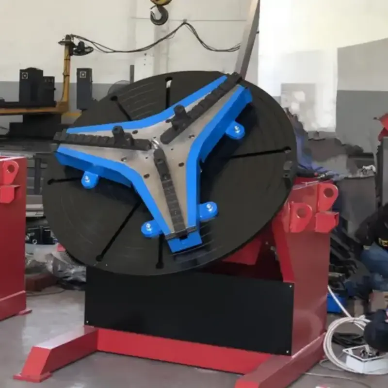
The WPT Series is specifically intended for use with welding positioners and other welding/cutting equipment. The catalogue also shows WPT chucks installed on positioners in actual application configurations.

High Clamping Force

Maximum specified clamping force ranges from 35 kN for WPT600 to 70 kN for WPT2000.

Large Size Range

Seven models are available:

WPT600 / WPT1000 / WPT1200 / WPT1500 / WPT1600 / WPT1800 / WPT2000

WPT Welding Chuck Specifications

ModelMax. Input TorqueMax. Clamping ForceLoad CapacityClamping Range
WPT600250 Nm35 kN1000 kgØ100–600 mm
WPT1000300 Nm45 kN1500 kgØ200–1000 mm
WPT1200300 Nm45 kN1500 kgØ200–1200 mm
WPT1500400 Nm65 kN2000 kgØ300–1500 mm
WPT1600500 Nm65 kN2000 kgØ300–1600 mm
WPT1800500 Nm65 kN2000 kgØ300–1800 mm
WPT2000600 Nm70 kN2000 kgØ300–2000 mm

These values are based on the supplied WPT Series product catalogue.

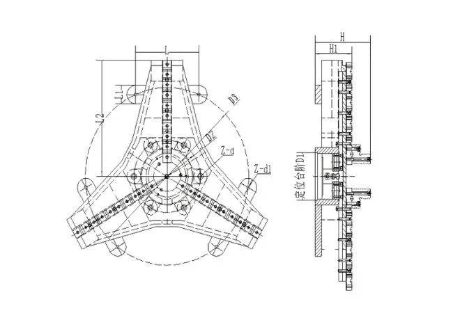
Mounting Dimensions

WPT-Series-Welding-Chuck
ModelD1 (H7)D2D3H1HL2L1LZ-d1Z-d
WPT600Ø205×10Ø27517526034560175—6-M12×150—
WPT1000Ø254×10Ø35017526055880300—6-M16×1506-M16×50
WPT1200Ø254×10Ø35017526065880300—6-M16×1506-M16×50
WPT1500Ø405×10Ø515230350800120500—6-M20×2006-M20×60
WPT1600Ø405×10Ø515230350850120500—6-M20×2006-M20×60
WPT1800Ø405×10Ø515230350900120500—6-M20×2006-M20×60
WPT2000Ø505×10Ø625230350900120500—6-M20×2006-M20×60

Dimensions in mm.

Note: Connection dimensions are provided for preliminary selection only. Final dimensions shall be confirmed according to the approved order drawing.
Designed for Welding Positioners

The WPT Series is specifically designed for integration with welding positioners and related welding or cutting equipment.

When mounted on a compatible positioner, the chuck centers and clamps the workpiece while the positioner provides the required rotation or angular positioning.

A typical setup is:

Workpiece → WPT Welding Chuck → Welding Positioner → Welding / Cutting Process

The catalogue shows WPT chucks used on both horizontal rotary positioners and tilting positioner configurations.

Typical Applications

  • Pipe Welding
    Suitable for holding large-diameter pipes during circumferential welding and positioning.
  • Cylindrical Workpieces
    The wide clamping range makes the WPT Series suitable for cylinders and other round fabricated components.
  • Welding Positioners
    Designed for installation on compatible positioners for workpiece centering, clamping and rotation.
  • Tank & Vessel Fabrication
    Larger WPT models provide the diameter range and specified load capacity required for many large cylindrical fabrication applications.
  • Welding & Cutting Equipment
    The series can be integrated with welding and cutting equipment requiring self-centering workholding.
WPT Welding Chucks Typical Applications

How to Select a WPT Welding Chuck

1. Determine the Workpiece Diameter

Identify the minimum and maximum diameter that needs to be clamped.

2. Check the Workpiece Weight

Compare the workpiece weight with the specified chuck capacity.

3. Determine the Center of Gravity

For long or heavy workpieces, provide the distance from the chuck face to the workpiece center of gravity.

4. Check the Positioner Capacity

The welding positioner must be capable of supporting the combined chuck and workpiece under the actual operating conditions.

5. Check the Mounting Interface

Confirm the mounting dimensions between the WPT chuck and positioner table.

6. Confirm Operating Orientation

Specify whether the chuck will operate horizontally only or will also be tilted by the welding positioner.

WPT Model Selection Guide

Maximum Required DiameterModel to ConsiderLoad Capacity
Up to Ø600 mmWPT6001000 kg
Up to Ø1000 mmWPT10001500 kg
Up to Ø1200 mmWPT12001500 kg
Up to Ø1500 mmWPT15002000 kg
Up to Ø1600 mmWPT16002000 kg
Up to Ø1800 mmWPT18002000 kg
Up to Ø2000 mmWPT20002000 kg

Note: This table is intended for preliminary diameter selection only. Final selection must also consider workpiece weight, center of gravity, clamping position, required clamping force and welding positioner capacity.

Load Capacity & Safety Considerations

The nominal load capacity of a WPT Welding Chuck should not be considered independently from the actual workpiece geometry and operating condition.

The catalogue specifies that users should consider an appropriate safety factor between the clamped workpiece weight and clamping force.

When the chuck and workpiece are tilted or rotated away from the horizontal position, the effective center-of-gravity distance changes. As a result, the allowable clamping/load capability may decrease.

Consider:

  • Workpiece weight
  • Workpiece diameter
  • Workpiece length
  • Center-of-gravity distance
  • Clamping position
  • Chuck orientation
  • Positioner load capacity
  • Positioner overturning moment

Important: A 2000 kg chuck rating does not automatically mean that every 2000 kg workpiece can be safely held in every orientation.

WPT vs. WP vs. WPS Welding Chucks

FeatureWPTWPWPS
Main FocusWide-range / large workpiecesLightweight general weldingLarge through-bore / high clamping force
Self-CenteringYesYesYes
Max. Catalogue RangeØ2000 mmØ950 mmØ1250 mm
Max. Specified Load2000 kg1000 kgNot specified
Max. Clamping Force70 kNListed in kg100 kN
Positioner ApplicationPrimary applicationYesYes
Largest ModelWPT2000WP900WPS1250

Request a Quote

Looking for a WPT Welding Chuck?

Send us your workpiece and welding positioner information for model selection and quotation.

WPT Model: __________
Workpiece Type: __________
Workpiece Diameter: __________ mm
Workpiece Length: __________ mm
Workpiece Weight: __________ kg
Center of Gravity from Chuck Face: __________ mm
Welding Positioner Model: __________
Positioner Load Capacity: __________ kg
Positioner Table Diameter: __________ mm
Operating Position: Horizontal / Tilting
Quantity: __________

For replacement applications, please send us photos, drawings and mounting dimensions of your existing chuck and welding positioner

Frequently Asked Questions

A WPT Welding Chuck is a self-centering workholding chuck designed primarily for welding positioners and welding/cutting equipment.

The standard range includes WPT600, WPT1000, WPT1200, WPT1500, WPT1600, WPT1800 and WPT2000.

The WPT2000 has a specified clamping range of Ø300–2000 mm.

WPT1500 through WPT2000 are specified with load capacities up to 2000 kg. Actual allowable loading depends on workpiece geometry, center of gravity and operating orientation.

The catalogue shows WPT chucks used with positioner equipment, including tilting arrangements. Actual allowable loading should be evaluated because tilting changes the workpiece center-of-gravity relationship and can reduce the available clamping/load capability.

Scroll to Top

Contact Us Now